pyrorisk.net · Fire Science & Risk Fire Safety Engineering
Critical Temperature: Why Steel Softens and Concrete Spalls
The 550 °C critical temperature of steel comes from a load ratio, not from metallurgy. Here is the real physics, and why hot concrete explodes.
Online: pyrorisk.net/blog/critical-temperature-why-steel-softens-and-concrete-spalls/
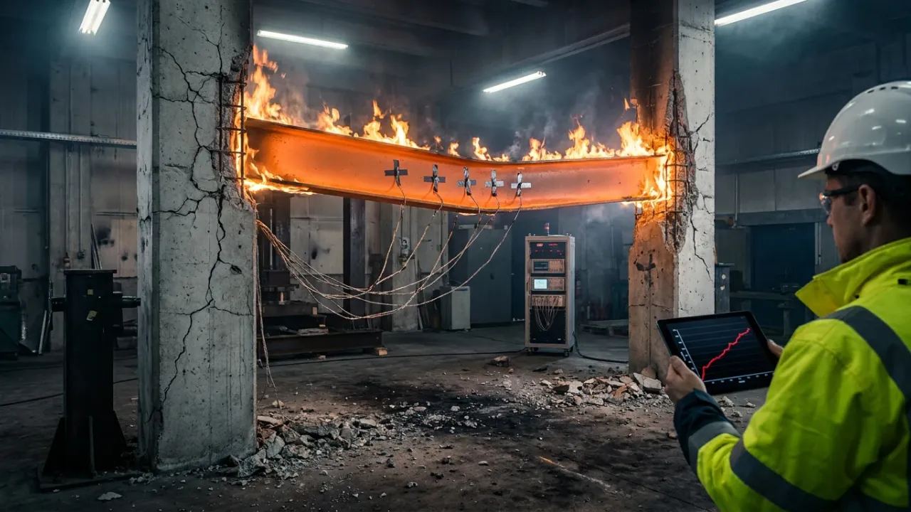
Ask a fire engineer what temperature structural steel fails at, and most will answer 550 °C. The number appears in textbooks, in training slides and in expert reports. Yet no metallurgist ever measured it. The 550 °C critical temperature falls out of one line of algebra in EN 1993-1-2. That line takes a single load level as its input. Change the load, and the answer moves by 200 °C. Concrete carries the opposite problem. It keeps useful strength to 500 °C, then throws lumps of itself across the room without warning. So this post takes both failures apart, and shows which numbers earn their place in design.
TL;DR
What the 550 °C critical temperature really means
- EN 1993-1-2 derives the critical temperature from the load ratio, not from metallurgy. A ratio of 0.6 returns 554 °C, which the profession rounds to 550 °C. A ratio of 0.2 returns 725 °C instead.
- Carbon steel keeps full yield strength to 400 °C, then drops to 78% at 500 °C and 47% at 600 °C. Stiffness falls much earlier, and only 31% survives at 600 °C.
- US practice sets the critical temperature by furnace limit rather than by formula. ASTM E119 ends the test at 538 °C average for columns, and 593 °C average for beams.
- Structural steel melts near 1,510 °C. No building fire reaches that point, so softening and thermal expansion drive every real failure.
Why concrete explodes instead of softening
- Explosive spalling couples two mechanisms: steam trapped behind a moisture clog, and restrained thermal stress running parallel to the hot face.
- Dense high-strength concrete suffers most, because low permeability traps the vapour. EN 1992-1-2 treats spalling as unlikely below 3% moisture by weight.
- About 2 kg/m³ of monofilament polypropylene fibre fixes it cheaply. The fibres melt near 160–170 °C and open vent paths for the steam.
- No deterministic spalling model exists. Engineers still predict it from test data, mix design and experience.
Where does the 550 °C critical temperature come from?
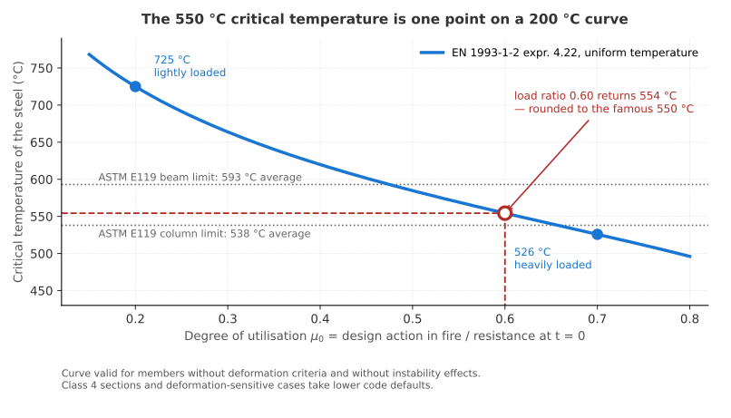
From a single equation in EN 1993-1-2, evaluated at one load level. Nothing in the metal marks 550 °C as a boundary.
Clause 4.2.4 gives the critical temperature of carbon steel under a uniform temperature rise. Expression 4.22 reads as follows.
Every term except the load ratio holds a fixed value. So the degree of utilisation carries all the meaning. It compares the design action in fire against the resistance of the member at the moment the fire starts.
Put 0.6 into expression 4.22, and it returns 554 °C. Rounding produced the number everyone quotes. Feed in 0.2 instead, and the critical temperature climbs to 725 °C. That 200 °C spread separates a member needing two hours of protection from one that may need none at all.
| Degree of utilisation | Critical temperature | Typical member |
|---|---|---|
| 0.70 | 526 °C | beam worked to its limit |
| 0.60 | 554 °C | the 550 °C convention |
| 0.50 | 585 °C | ordinary office beam |
| 0.40 | 620 °C | column with spare capacity |
| 0.30 | 664 °C | member sized by stiffness |
| 0.20 | 725 °C | member sized by deflection |
Why does the load ratio move the answer so far?
Because fire uses a different load case from ambient design. Accidental combinations strip out most partial factors, so members rarely work as hard in fire as at room temperature.
The reduction factor for the fire load level gives the ratio between the two cases. EN 1993-1-2 allows 0.65 as a safe default outside storage occupancies. Yet a typical office, with imposed load equal to dead load, lands near 0.53. The Steel Construction Institute publishes tables from the same expression. For protected beams supporting a slab, the SCI tables run from 558 °C at a ratio of 0.7 up to 750 °C at 0.2. Beams without a slab sit lower, from 526 °C to 725 °C.
Two caveats travel with the critical temperature curve. First, deformation-sensitive members take lower code defaults, and some tension members work to just 350 °C. Second, the expression assumes uniform temperature and no instability. Slender sections and columns therefore need the full resistance check instead.
Why does US practice fix 538 °C instead?
Because ASTM E119 sets pass/fail thermocouple limits rather than a formula. The furnace protocol, not the load ratio, ends the test.
| Member | ASTM E119 limit | Basis |
|---|---|---|
| Steel column | 538 °C (1000 °F) | average of all points |
| Steel beam | 593 °C (1100 °F) | average of all points |
| Steel beam over 4 ft on centre | 704 °C (1300 °F) | single-point maximum |
| Reinforcing steel in concrete | 593 °C (1100 °F) | average, first hour |
| Cold-drawn prestressing steel | 427 °C (800 °F) | average, first hour |
Those limits come from the ICC-ES summary of ASTM E119. The physics behind them matches the Eurocode curve, because both track the same strength loss. Only the wrapper differs. One approach calculates, while the other watches a thermocouple. Our post on reaction to fire versus fire resistance covers why furnace ratings mean so little outside the furnace.
Does structural steel ever melt in a building fire?
No. Carbon steel melts near 1,510 °C, and no protected member in a building fire comes close.
NIST made the point plainly in its World Trade Center investigation FAQ. Fire weakens steel; it does not liquefy it. Softening happens gradually instead, and it starts long before anything glows. At 550 °C carbon steel still holds roughly 60% of its room-temperature yield strength. A member working at 60% of capacity therefore runs out of margin at exactly that point. The coincidence looks like a material property, yet it only reflects the arithmetic.
Why does steel lose strength before it melts?
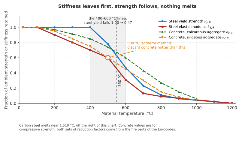
Because heat frees the dislocations that carry load, long before the crystal lattice comes apart. EN 1993-1-2 Table 3.1 puts numbers on that loss.
| Steel temperature | Yield strength | Proportional limit | Elastic modulus |
|---|---|---|---|
| 20 °C | 1.000 | 1.000 | 1.000 |
| 200 °C | 1.000 | 0.807 | 0.900 |
| 400 °C | 1.000 | 0.420 | 0.700 |
| 500 °C | 0.780 | 0.360 | 0.600 |
| 600 °C | 0.470 | 0.180 | 0.310 |
| 700 °C | 0.230 | 0.075 | 0.130 |
| 800 °C | 0.110 | 0.050 | 0.090 |
| 1000 °C | 0.040 | 0.025 | 0.045 |
| 1200 °C | 0.000 | 0.000 | 0.000 |
Two patterns stand out. Yield strength holds at 1.00 all the way to 400 °C, then collapses across the next 200 °C. Stiffness never holds at all, because the elastic modulus starts falling by 100 °C.
Which goes first, strength or stiffness?
Stiffness, by a wide margin. At 600 °C a member keeps 47% of its yield strength, yet only 31% of its elastic modulus.
That gap decides the failure mode, so one critical temperature cannot cover both checks. Buckling depends on stiffness, so slender columns and Class 4 sections lose capacity faster than the yield numbers suggest. Deflection follows the same rule. A beam at 500 °C carries 78% of its cold strength on 60% of its cold stiffness, so it sags long before it breaks.
The proportional limit drops fastest of all. By 200 °C it already reads 0.807, and by 400 °C only 0.420. The clean yield plateau therefore disappears above roughly 100 °C, and EN 1993-1-2 replaces it with an elliptical transition between the proportional limit and the effective yield strength. Hand calculations that assume elastic-perfectly-plastic behaviour will overstate what a hot member can do.
What changes inside the metal?
Three regimes, each with its own mechanism. Temperature alone decides which one governs.
Between 100 and 300 °C, mobile carbon and nitrogen atoms pin moving dislocations. Metallurgists call that interaction dynamic strain ageing, or blue brittleness, and it briefly raises strength while cutting ductility. Above roughly 400 to 450 °C the balance flips. Dislocations climb, recovery sets in, carbide pinning fails, and creep takes over as the controlling process.
Creep itself changes character with temperature. Below about 650 °C, dislocation processes control it, according to recent creep work in the Fire Safety Journal. Above 650 °C, diffusion and grain-boundary sliding dominate, and damage accumulates far faster. The Eurocode stress-strain model folds creep into its curves for heating rates between 2 and 50 K per minute. Push outside that band, either with a slow smouldering fire or a hydrocarbon jet, and the model loses its footing.
Do all steels behave alike?
No. Cold-worked and high-strength grades lose more, and they lose it earlier.
Prestressing steel sets the harsh end of the range. EN 1992-1-2 assigns a critical temperature of 400 °C to prestressing bars and 350 °C to wires and strands, against roughly 500 °C for ordinary reinforcement. Cold-formed steel gets separate treatment in EN 1993-1-2 Annex E, and in AISI S100 across North America.
Modern high-strength steels bring a quieter problem. Grades such as S460 and S690 buy their ambient strength from microstructures that heat undoes: fine precipitates, controlled rolling, quenched and tempered phases. So they often retain a smaller fraction of their strength than plain mild steel. A designer who swaps S355 for S690 to save weight also cuts the fire margin, unless the check runs again at temperature.
Why does thermal expansion often beat strength loss?
Because restraint turns a temperature rise into stress, with no extra load at all. A fully restrained member generates that stress from the first degree, far below any critical temperature.
Carbon steel expands by about 12 × 10⁻⁶ per kelvin near room temperature, rising to roughly 14 × 10⁻⁶ per kelvin across the fire range. Free expansion costs nothing. Block it, though, and the member carries the stress it would otherwise have released by growing.
Run that for a 100 K rise. Multiplying 210 GPa by 12 × 10⁻⁶ per kelvin and by 100 K gives 252 MPa. Such a figure already exceeds the 235 MPa yield strength of S235 steel, at a temperature where every reduction factor still reads 1.00. Real frames never restrain a member perfectly, so the true force stays lower. Even so, the scale explains why connections fail before members do.
Thermal bowing adds a second effect. A column heated on one face curves toward the fire, which shifts the load off its axis. Beams then push their supporting columns outward while heating, and pull them inward while cooling. Many recorded connection fractures happen during that cooling phase, long after the fire peaks.
How fast does steel reach its critical temperature?
The section factor sets the pace, along with the protection and the fire itself. A bare member can arrive within ten minutes, while a protected one takes hours.
EN 1993-1-2 treats an unprotected member as a lump at uniform temperature. Each time step adds heat from the fire, then spreads it through the mass.
The ratio of heated surface area to volume does the work. A light beam with thin flanges heats far faster than a stocky column of the same grade. The shadow factor then trims the radiation that a concave profile blocks from reaching itself.
Unprotected steel under the standard fire reaches its critical temperature in roughly 10 to 20 minutes. One published time-to-temperature relationship puts an unprotected 406 × 178 × 60 UB at 620 °C after about 14 minutes. Protection buys the remaining time before the critical temperature arrives. Sprayed materials, intumescent coatings, boards and concrete encasement all add an insulation term, plus a factor for the heat the protection itself absorbs.
US practice reaches the same place by a different route. AISC 360-22 Appendix 4 now carries both the prescriptive path and the performance path, using W/D and A/P ratios instead. The prescriptive route leans on IBC Chapter 7 and tested UL assemblies. The performance route uses ASCE/SEI 7-22 Appendix E and the calculation methods in ASCE/SFPE 29, described in NIST Technical Note 1842.
What did the full-scale fires teach?
A frame behaves nothing like an isolated member. Steel beams passed 1,000 °C at Cardington, and the building simply stood there.
BRE and British Steel burned six compartments in an eight-storey composite frame at Cardington between 1995 and 1996. Unprotected beams ran far past every critical temperature in the code. Wald and colleagues recorded a maximum steel temperature of 1,087.5 °C after 57 minutes, on the bottom flange of one beam. At 900 °C the steel deck had lost about 94% of its strength.
Nothing collapsed. Once the beams gave up, the composite slab picked up the load through tensile membrane action, and the reinforcement carried it back to the cooler perimeter. Those secondary beams had run at a load ratio near 0.44, under a floor load of about 5.48 kN/m². Isolated-member design would have written them off half an hour earlier.
Why did WTC 7 collapse below 400 °C?
Because thermal expansion, not strength loss, pushed a girder off its seat at Column 79. NIST placed the critical damage well below the range where yield strength matters.
The NIST WTC 7 investigation identified ordinary office fires as the cause, with no diesel, no explosives and no melted steel. Long-span floor beams grew as they heated. That growth walked a girder past its seat, a floor dropped, and progressive collapse followed. The building became the first tall structure known to fall primarily because of fire.
Temperature evidence supports the account. NIST screened recovered steel from the towers in NCSTAR 1-3D, judging exposure from paint condition and microstructure. Only a small number of pieces had ever passed 250 °C. So the lesson stands on its own: a connection can fail at 300 °C while the member beside it still holds full strength.
What do Broadgate, Windsor and Plasco add?
Three more data points, and they disagree with each other. Protection, frame layout and connection detail decide each outcome.
At Broadgate Phase 8 in 1990, fire ran through a partly built steel frame carrying no applied protection. Members distorted badly, yet the frame held, and repairs followed. The Windsor Tower in Madrid then burned for some 19 hours in February 2005. Unprotected perimeter columns above the 17th-floor transfer structure buckled, and the outer floor spans fell. The concrete core and the protected steel below survived.
Plasco in Tehran ended differently. In January 2017, fire in the 16-storey steel building killed 22 people, including 16 firefighters, and brought the whole frame down. Investigators pointed at connection failure and catenary action in the sagging floors, rather than at simple softening. Together these cases pushed the discipline toward frame analysis, travelling fires and performance-based design, which our post on ASET versus RSET picks up from the occupant side.
Why does concrete explode instead of softening?
Because concrete traps steam. Water inside the pores turns to vapour faster than the vapour can escape, and the surface layer leaves violently.
Explosive spalling throws fragments off a heated face, sometimes hard enough to cross a room. It strips cover from reinforcement, exposes bars to the flames, and can cut a section’s capacity within minutes. Two mechanisms run together here, and the literature still argues about their relative weight.
What builds the pore pressure?
A moisture clog. Steam driven inward meets cooler concrete, condenses, and forms a saturated band that blocks any further escape.
Harmathy named the mechanism decades ago, and it still carries his label. Behind the clog, pressure rises until tensile stress exceeds the tensile strength of the concrete, which sits near a tenth of its compressive strength. The second mechanism needs no water at all. Restrained thermal dilation puts the hot surface into biaxial compression parallel to the face, which generates tension perpendicular to it, and the layer peels away.
Neither mechanism explains everything alone. Jansson and Boström watched specimens spall below 0.5 MPa of pore pressure, while others survived above 3 MPa. Bažant argued from the other direction, treating thermal stress as the usual trigger and pore pressure as an aggravating factor. A review of spalling theories sets out the current consensus, which treats the two as coupled.
Which concrete spalls worst?
Dense, strong, young and wet concrete. High-strength and ultra-high-performance mixes top the list, because low permeability leaves the steam nowhere to go.
Silica fume and a low water-to-cement ratio give those mixes their strength and their vulnerability at once. Normal-strength concrete vents steam through a coarser pore network, so pressure stays lower. EN 1992-1-2 treats explosive spalling as unlikely below 3% moisture by weight for grades below C80. That threshold deserves suspicion, since spalling has occurred below it, and national annexes place the line anywhere from 2% to 4%.
| Factor | What raises the spalling risk |
|---|---|
| Compressive strength | higher grade, denser matrix |
| Moisture content | above roughly 3% by weight |
| Heating rate | hydrocarbon and tunnel curves |
| Load and restraint | higher compressive stress at the face |
| Section size | thicker members, longer moisture path |
| Aggregate | siliceous, and thermally unstable types |
Do polypropylene fibres work?
Yes, and cheaply. About 2 kg/m³ of monofilament polypropylene fibre stops most explosive spalling in high-strength concrete.
The mechanism disarms itself at the right moment. Polypropylene melts near 160 to 170 °C, well below the temperature where spalling starts. Each molten fibre leaves a channel, those channels connect, permeability jumps, and steam vents instead of building pressure. EN 1992-1-2 points to roughly 2 kg/m³ of fibre with a diameter of 50 μm or less.
Field dosages run from 1 to 3 kg/m³. Around 2 kg/m³ at about 20 mm length works up to roughly 100 MPa under the standard fire, according to a review of fibre performance. Ultra-high-performance concrete resists even that, and specimens have spalled at 3 kg/m³. Dispersion matters as much as dosage, since clumped fibres leave unprotected patches. Air entrainment, sacrificial layers and thermal barriers then cover the remaining cases.
Why do tunnel fires make spalling worse?
Because hydrocarbon and tunnel curves heat the surface far faster than the standard building fire. Thermal shock does its damage in the first half hour.
The Dutch RWS curve reaches about 1,350 °C within 60 minutes, and the German RABT-ZTV curve hits 1,200 °C in roughly 5 minutes. Compare that with the standard curve, which needs about 90 minutes to pass 1,000 °C. Linings therefore see steep gradients, high restraint and heavy spalling, as the Channel Tunnel fires of 1996 and 2008 both showed.
Dosage follows the exposure. Guidance moves from roughly 1 kg/m³ of polypropylene fibre for standard-fire exposure up to about 3 kg/m³ for RWS. Our post on road tunnel fire risk covers the design fires behind those curves, while how hot fire really gets explains why a hydrocarbon flame outruns a wood crib.
How much strength does hot concrete keep?
More than steel, and for longer. Concrete keeps 60% of its compressive strength at 500 °C with siliceous aggregate, and 74% with calcareous.
| Concrete temperature | Siliceous aggregate | Calcareous aggregate |
|---|---|---|
| 20 °C | 1.00 | 1.00 |
| 200 °C | 0.95 | 0.97 |
| 400 °C | 0.75 | 0.85 |
| 500 °C | 0.60 | 0.74 |
| 600 °C | 0.45 | 0.60 |
| 800 °C | 0.15 | 0.27 |
| 1000 °C | 0.04 | 0.06 |
Calcareous aggregate wins at every step above 200 °C. Chemistry sets the limits underneath those numbers. Portlandite dehydrates between roughly 450 and 550 °C, and calcium carbonate decomposes near 800 °C. Neither reaction reverses on cooling, so a fire-damaged member never recovers its original strength.
Design rarely uses the full curve. The 500 °C isotherm method of EN 1992-1-2 Annex B.1 discards every part of the section hotter than 500 °C, then takes the remainder at full strength. Crude, yet it lands close enough for most beams and columns. Reinforcement gets the real attention. So the critical temperature of an ordinary bar sits near 500 °C, where half its yield strength has already gone. Cover depth therefore becomes the design variable, handled by tabulated data in EN 1992-1-2 Section 5, and by ACI/TMS 216.1 in the US.
Where does the critical temperature approach fall short?
In four places. Each one can move the answer further than the safety margin allows.
- The standard fire curve resembles no real fire. ISO 834 and ASTM E119 rise forever and never decay. Real compartments burn out, and large open floors burn in patches rather than all at once.
- Travelling fires break the uniform assumption. Stern-Gottfried and Rein modelled a near-field around 1,200 °C moving across a floor, with a cooler far-field behind it, in the Fire Safety Journal. A long, cooler exposure can punish a member more than a short, hot one.
- Furnaces disagree with each other. Repeat one assembly in two laboratories and the ratings differ, a problem our post on fire tests that disagree explores from the reaction-to-fire side.
- Spalling has no deterministic model. Engineers still predict it from tests, mix data and experience, and most routine designs never model it at all.
One deeper question stays open. A single critical temperature makes protection specifiable, which carries real value on a live project. Yet it hides the load dependence, it hides the faster loss of stiffness, and it hides thermal expansion altogether.
How should you use the critical temperature in practice?
Treat it as an output, never as an input. Five rules cover most projects.
On the steel
- Calculate the load ratio before quoting any temperature. Work out the degree of utilisation for the actual fire load combination, then read the critical temperature from expression 4.22. A lightly loaded member may need far less protection than the 550 °C default implies, while a heavily loaded one may need more.
- Check stiffness separately from strength. For columns, slender sections and any deflection limit, run the check on the elastic modulus. The 31% remaining at 600 °C governs long before the 47% of yield strength does.
- Model the connections and the restraint. Where a frame restrains expansion, add the thermal force to the check. A 100 K rise can generate 252 MPa, which no member-by-member calculation will ever reveal.
On the concrete
- Specify polypropylene fibres by exposure, not by habit. Use roughly 2 kg/m³ for high-strength concrete under a standard fire, and about 3 kg/m³ against tunnel curves. Then verify with a test on the actual mix, because ultra-high-performance concrete can still spall.
- Design the cover for the bar, not for the surface. Keep reinforcement below 500 °C using tabulated cover or the 500 °C isotherm method. Assume spalling removes cover unless fibres or test data say otherwise.
Key takeaways
The 550 °C critical temperature earns its place as shorthand and nothing more. It comes from expression 4.22 of EN 1993-1-2 at a load ratio of 0.6, where the formula returns 554 °C. Move that ratio to 0.2, and the same steel serves to 725 °C. US practice lands on similar figures through furnace limits of 538 and 593 °C, by an entirely different road.
The physics underneath tells a more useful story. Stiffness goes before strength, creep takes over above 400 to 450 °C, and nothing melts until 1,510 °C. Cardington showed frames surviving past 1,000 °C through membrane action, while WTC 7 fell from thermal expansion below 400 °C. So the temperature of one member predicts far less than the behaviour of the frame around it.
Concrete fails by the opposite route. It holds 60% of its strength at 500 °C, then removes its own cover without warning when trapped steam and restrained thermal stress combine. Two kilograms of polypropylene fibre per cubic metre solves most of that. Beyond it, run the numbers for your load ratio, your restraint and your mix, then treat every single-number rule as a starting point.
Cite this articleHow to cite
Dinh, D. C. (2026, September 13). Critical Temperature: Why Steel Softens and Concrete Spalls. PyroRisk. https://pyrorisk.net/blog/critical-temperature-why-steel-softens-and-concrete-spalls/
Recent posts
Featured posts
Categories
Comments
Related posts
Fire Safety Engineering
2-Hour Fire Wall: What a Fire Resistance Rating Measures
A 2-hour fire resistance rating means a wall survived a 1918 furnace curve, not a real fire. Here is what the test proves, and where it falls short.

Fire Safety Engineering
ASET vs RSET: The Inequality Behind Every Evacuation Plan
ASET vs RSET decides whether a building passes. Here come the timeline, the tenability limits, the equations, and the one term that swings the answer most.
Fire Safety Engineering
Ionization or Photoelectric Smoke Alarm? Why Experts Split
Ionization alarms beat a photoelectric smoke alarm by seconds in flaming fires, then lose by 30 minutes in smoldering ones. Here is why experts still split.